Simulation of UML descriptions
Simulation of UML descriptions with UMLAUT Simulator
Introduction
This simulator is able to transform an initial UML model (class, state-charts and deployment diagram) into an executable one (in the form of a labelled transition system (IOLTS))
linkable to validation, simulation tools and test
generation tools.
The following sections describe the steps to use UMLAUT/Simulator from the
modeling to the validation of a system.
The first steps are realizable with
the UMLAUT GUI available in the Simulator package.
For the last ones you have to use the batch commands included too in the Simulator package.
At the end, we present a case study.
Launch the GUI to create a new model or load (from the native UP format
or from XMI) an existing model.
Eventually, rename the "root" package given a new name <model-name>.
Save your model in a file called <model-name>.uml (give the same name as the name of the root package). We recommend to often make copies of your model before saving.
The modeling consists in :
- describing the functions of the system with Use Cases, identifying the actors which model the environment [fig 1].
- modeling the static part of the system with a Class Diagram (both active and passive classes) [fig 2].
- modeling the behavior of the system with StateChart Diagrams, attaching a
statechart to each class of the system and to each actor.
Some restrictions must be applied :
- a transition is a sequence of atomic actions
- the effects of actions must be directly expressed in the target language (in our case Eiffel).
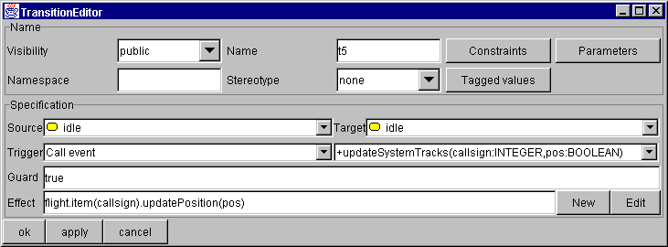
In Eiffel, the action effect is described as a sequence of <name of associationEnd>.<name of operation>(<parameter1> , <parameter2>... ); or <name of associationEnd>.item(<index>).<name of operation> (...); when the multiplicity of the associationEnd is greater than 1 [fig 3]
- all parameters of messages sent by the environment (i.e. sent by actors) must be instanciated.
- defining an initial configuration for the system with a deployment diagram [fig 4].
We present here a preliminary support to automatically generate test purposes (in BCG format) from UML.
To describe simple test purposes with UMLAUT, we suggest the use of the UML
sequence diagram notations : a scenario is used to express a
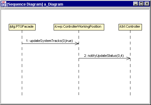
property for which we want to generate a test (see an example [fig 5]). Note: have a look to the GUI manual page
about the Sequence Diagrams editor in UMLAUT.
We propose the following steps :
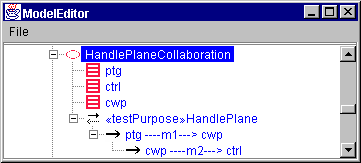
- create a collaboration, attached to a given context (for example under a use case) [fig 5a].
- create the objects (ClassifierRoles) involved in the collaboration, with
one simplification: the name of a classifier role must be the same as the name
of the instance (i.e. the object in the deployment diagram) which plays this
role.
- create interactions which will describe test purposes, and attach the
stereotype <<testPurpose>> to each one (if necessary, add the
stereotype <<testPurpose>> to the set of existing stereotypes under
the top level package). You can also attach a scenario view (ie. a Sequence
Diagram) using the item "Draw as scenario" and create/edit new elements (such
as Messages) on the diagram directly [fig 5b].
- add/edit/modify as long as it's necessary...
- produce the BCG automatons (visualizable with CADP editors
such as bcg_edit) using the item "Export in BCG" of the pop-up menu attached to the interactions in
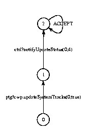
the browser. Save them in BCG files (<tp-name>.bcg) [fig 6].
First, you must conform to the installation requirements described in the text file INSTALL provided in the simulator package.
Then, in a command line window, you can execute the scripts uml2c and uml.open.
The script uml2c :
uml2c <model-name>.uml
- applies the VALOODER framework to transform the model into an executable one (using the UMLAUT command "VALOODER").
- generates the Eiffel code (using the command "EIFFEL") and compiles it in C thanks to SmallEiffel compiler.
You have to write a loadpath.se file necessary to SmallEiffel: this file must indicate the paths to the produced Eiffel classes, to the directories rts/ and ${SMALLEIFFEL}/lib_std/.
- produces the main Eiffel class (class of initial configuration) from the deployment diagram,
- and generates (using the command "TESTING") the files necessary to a connection with TGV and a set of test
purposes: some simple test purposes deduced from the UML model and some generated from the UML interactions stereotyped with <<testPurpose>>.
The script uml.open allows to apply V & V tools, such as the interactive
simulator xsimulator, the exhaustive simulation engine generator and the
test generation tool TGV (all included in the CADP tools-box) from the UML model.
For example for xsimulator:
uml.open <model-name>.uml xsimulator
For example for TGV:
uml.open <model-name>.uml tgv [tgv_options] <tp-name>.bcg
In our ATC model, the environment is modeled by three actors: the human Controller (of our ATC), the PTGFacade (the radar) and the CCGFacade (a controller of an other ATC). The system consists of four classes: Flight and FlightPlan, used to store flight data, ControllerWorkingPosition and FlightPlanManager which control the system and interact with the environment.
[fig 1] The following use case expresses that a plane entering the zone can be handled by the system.

[fig 2] This is the static view of the ATC. 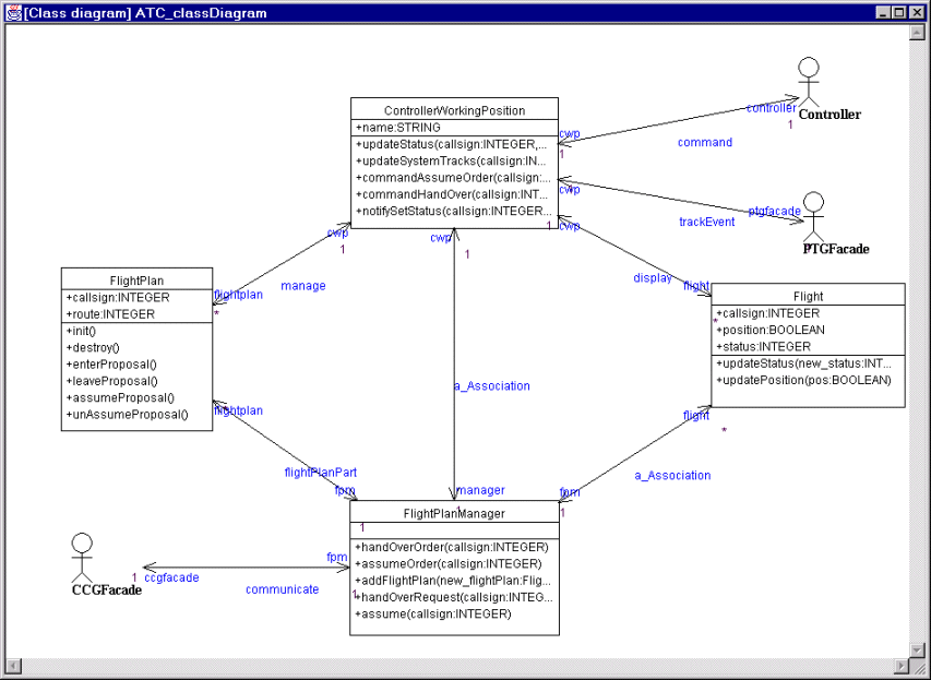
[fig 3] The next figure presents the transition editor for the capture of StateCharts.
[fig 4] The following view is the initial configuration of our system. The deployed system knows of two flights (each with an associated flight plan), initially located out of the area managed by the ATC.

[fig 5 a-b] With the test purpose given in this figure, we want to generate a test checking that the flight 0 will be correctly assumed by the ATC (i.e. that the controller ctrl will be notified that the flight status is updated with the value 4) when the flight enters the ATC zone (i.e. when the radar ptg indicates the flight new position true meaning `in zone'').
[fig 6] View (with bcg_edit) of the test purpose automaton produced from the UML messages sequence.